 EN
Industrial Manufacturing Plant: Steel Building Specs
For an industrial manufacturing plant, the steel package should start with the production process, not a catalogue span. A light assembly line, a metal-fabrication shop and a chemical or metallurgical facility can all occupy steel buildings, yet their load paths, clearances, corrosion exposure and foundation interfaces are very different. The better question is not “Which building is strongest?” It is which specification supports the process without building in avoidable cost or site risk.
As a steel-structure engineering consultant, I would first map material flow, equipment weights, crane travel, utilities and future expansion. Most buyers initially assume a familiar portal-frame span will work—until a crane runway, a tall process vessel or a line of equipment foundations changes the column and haunch design. This is why an industrial manufacturing plant needs a brief that is more specific than floor area and eave height.
Start with the manufacturing class
Light assembly and packaging
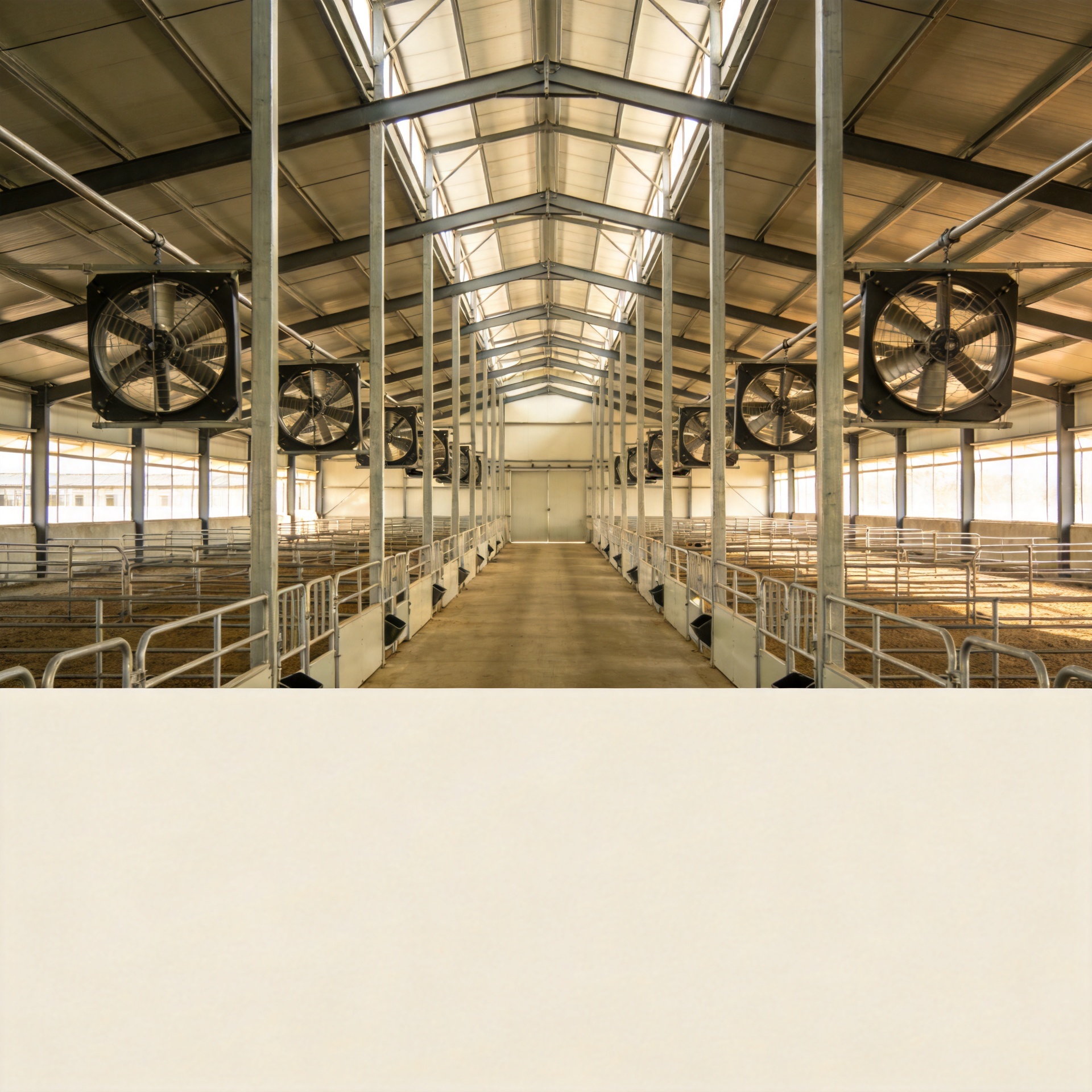
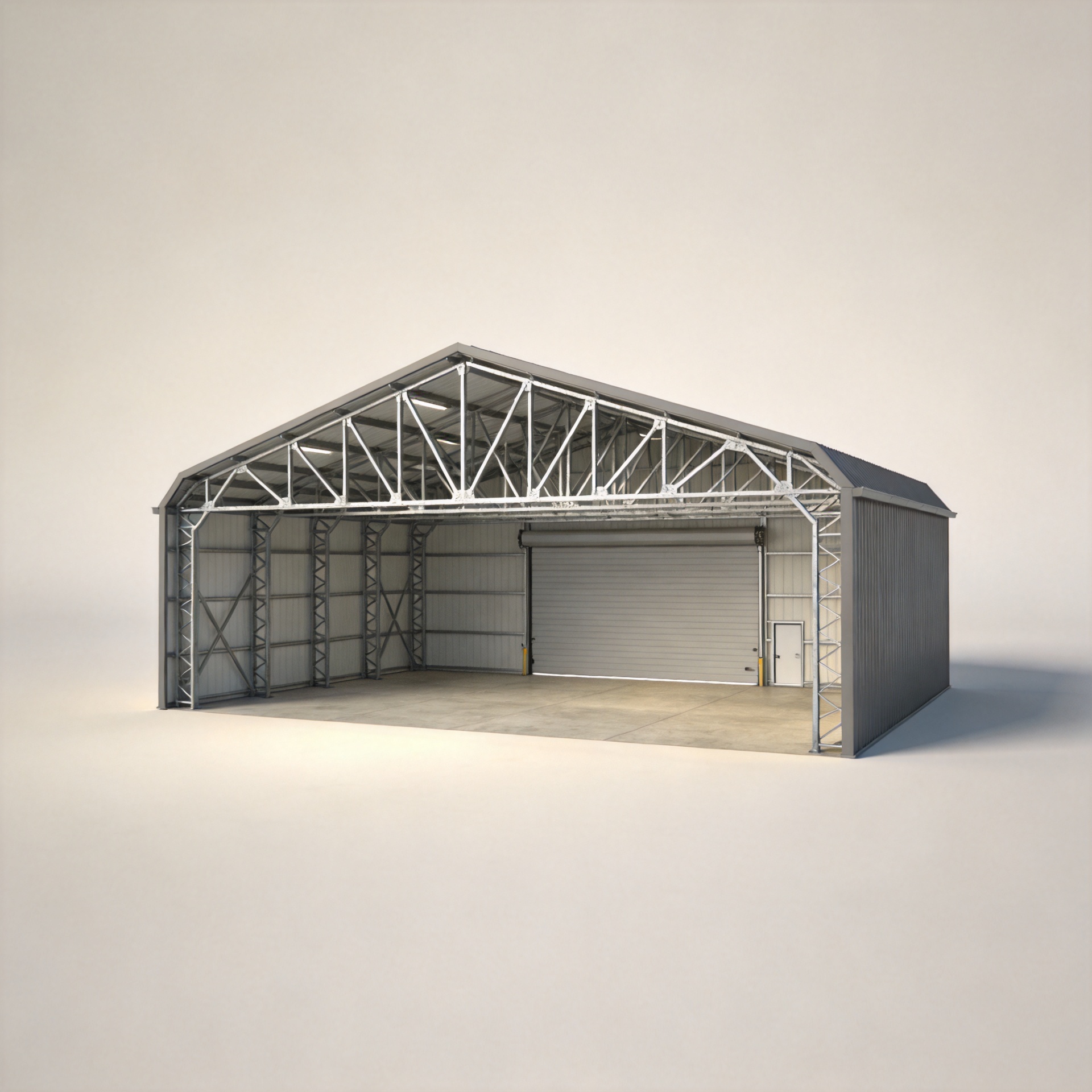
Light assembly, packing and clean, low-load processes commonly prioritize clear working space, daylight, ventilation and fast enclosure. A clear-span portal frame can keep internal columns away from conveyor routes and flexible work cells. The roof and wall package may be selected around thermal comfort, local rainfall and ventilation requirements rather than heavy process loading. If dispatch doors are frequent, specify the opening dimensions, wind exposure and duty cycle of each industrial roller shutter early; a door opening is a framing condition, not a late architectural add-on.
Medium metal fabrication
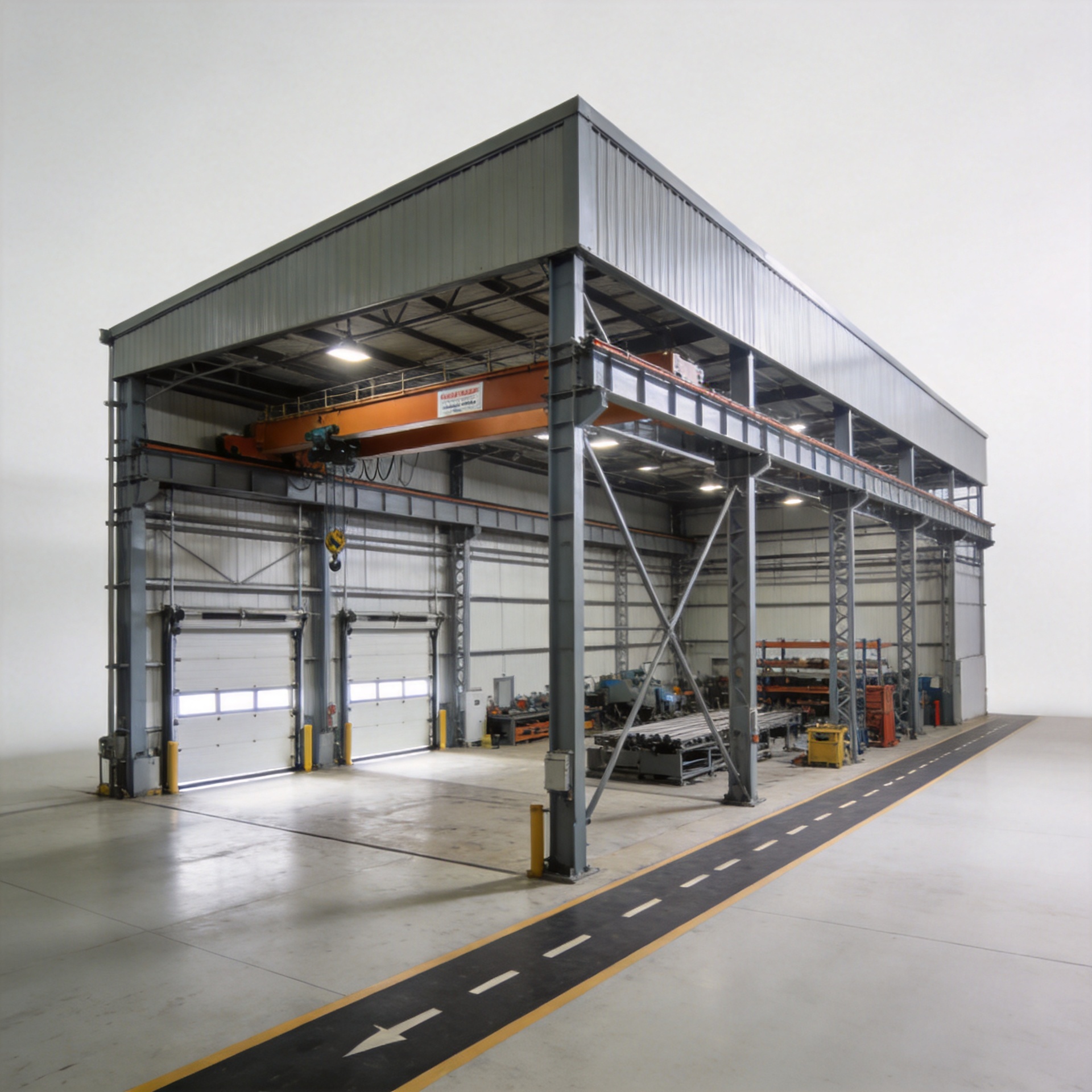
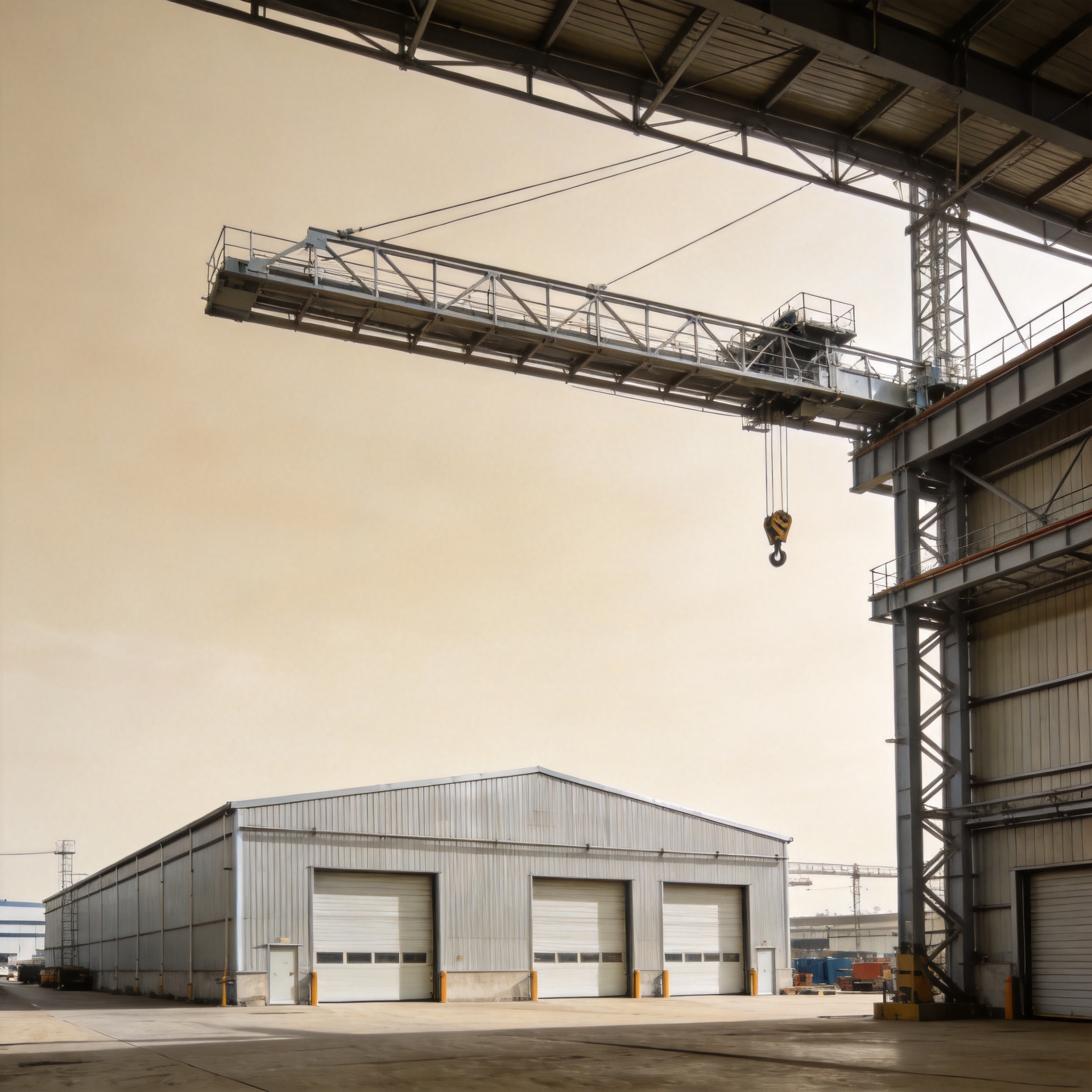
Fabrication shops usually make crane operation, concentrated equipment loads, vibration and vehicle circulation central to the design. Here, an industrial manufacturing plant often benefits from a grid that coordinates crane columns, loading bays and future machine positions. Crane capacity alone is not sufficient information. The engineer also needs runway span, rail level, crane class, wheel loads, impact effects, hook approach, duty cycle and whether one or two cranes can operate in the same bay. Crane-beam deflection can become visible under a rated lift, so it should be checked as part of the serviceability design rather than treated as a cosmetic concern after erection.
Heavy chemical, metallurgical or high-heat work
Heavy process facilities can require tall bays, substantial crane systems, local platforms, pipe supports and equipment foundations that must remain independent from the building steel where appropriate. Heat, dust, chemicals, moisture and maintenance access can be more decisive than the nominal building span. For this type of industrial manufacturing plant, separate process engineering from structural assumptions: identify all imposed loads, thermal effects, dynamic loads, corrosion zones and access routes before member sizing begins.
Choose the steel grade as part of the load strategy
Q355B, Q420B and Q460D are high-strength structural-steel options that may be considered where the verified design loads, member geometry, fabrication route and applicable project standard support their use. The number in a grade designation is not a shortcut to a complete member design. Yield properties can depend on thickness and the governing material standard, while weldability, toughness requirements, connection details and availability also influence the practical choice.
For many routine portal-frame components, Q355B may provide an effective starting point. Q420B or Q460D may be evaluated for heavily loaded members, long-span conditions or crane-related demand when the structural engineer confirms the complete design case. Higher strength is not automatically a better building: deflection, stability, connections, fabrication tolerances and transport limits can govern before nominal material strength does. Ask the supplier to state the proposed grade by member group, the assumed load basis and the documents that will be issued for review.
Set span, column grid and crane arrangement together
A single-span building removes interior columns and can simplify uninterrupted flow, storage and large-machine placement. A multi-span arrangement can reduce individual rafter demand, create separated process bays and align crane routes with production zones. Neither is universally better. The right answer changes with usable width, required headroom, crane configuration, site boundary constraints and the value of unobstructed space.
- Span: define it from process clearance and circulation, then validate member depth, roof drainage and erection constraints.
- Column spacing: coordinate it with cladding modules, door locations, mezzanines, loading areas and machine layout; an optimized grid is not simply the widest possible bay.
- Crane beams: identify crane data before the general arrangement is frozen, including future capacity allowances where expansion is credible.
- Foundations: reserve locations and load data for presses, furnaces, tanks or mills. Building foundations and equipment foundations may need different settlement, vibration or isolation treatment.
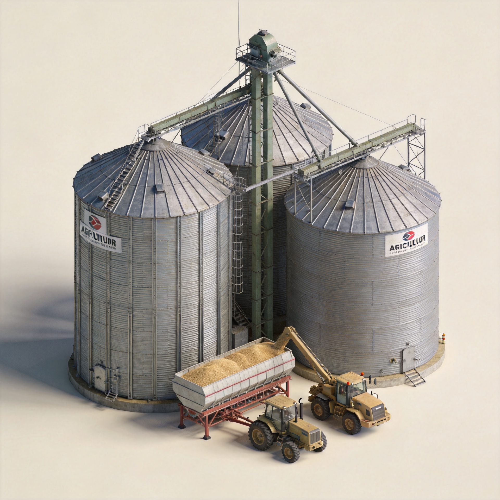
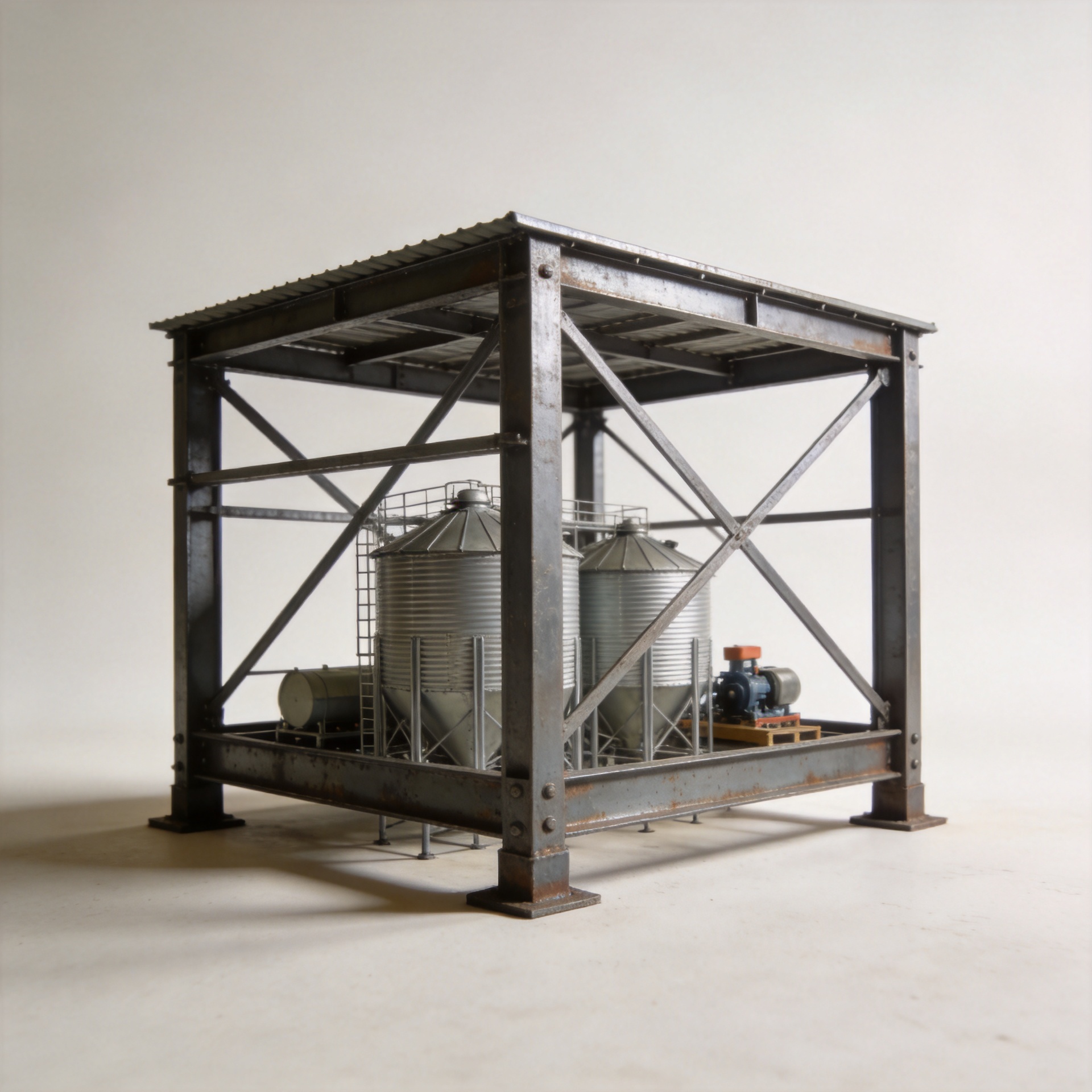
A flour mill building illustrates the point well. Even when the shell looks like a conventional workshop, processing equipment, vertical conveyance, dust-control systems, platform loads and cleaning access can drive the grid, elevation and foundation plan. Treating it as a generic shed can lead to disruptive changes once equipment drawings arrive.
Specify enclosure and corrosion protection by exposure
Wall and roof systems should answer operational needs: insulated sandwich panels for a controlled indoor environment, metal cladding where thermal performance is less demanding, daylight panels where appropriate, and ventilation provisions sized around heat or process emissions. The enclosure must also coordinate with fire, drainage, maintenance and local code requirements.
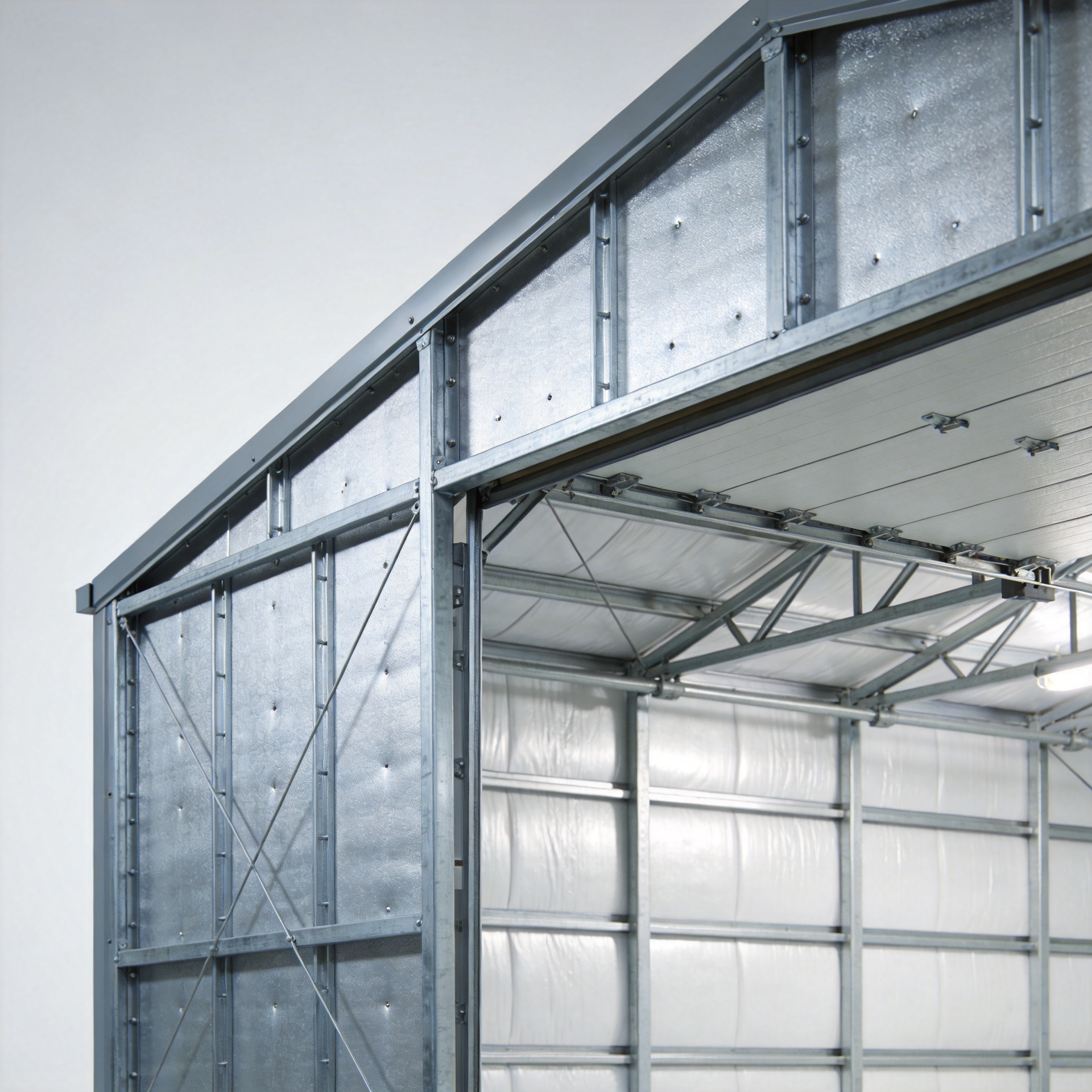
For coastal, chemical, humid or wash-down conditions, do not accept a generic “anti-rust paint” description. Define the exposure zones and ask for a corrosion-protection system tied to an applicable framework such as ISO 12944, including surface preparation, coating layers, dry-film-thickness requirements, repair method and inspection records. Hot-dip galvanizing, a specified paint system, or a combined approach may be suitable depending on the environment and detailing. Water traps, unsealed crevices and inaccessible steel can undermine a good coating system; design details matter as much as the coating name.
Why prefabricated steel helps overseas projects
For overseas manufacturers and engineering traders, prefabrication can move cutting, drilling and controlled shop work away from a constrained jobsite. Clearly marked components, shop drawings, anchor-bolt plans, packing lists and erection manuals help local teams coordinate the build. That does not remove site work, permits or foundation responsibility. Late approval of anchor-bolt drawings can hold the schedule longer than steel fabrication.
When evaluating an industrial real estate development or a single owner-occupied plant, compare total project readiness rather than only steel tonnage. The supplier should be able to clarify scope boundaries for primary steel, secondary framing, roof and wall systems, doors, fasteners, drawings and erection support. A complete, reviewable scope makes quotation comparisons more meaningful and reduces omissions at handover.
Turn the concept into a procurement-ready brief
Before requesting a final quotation for an industrial manufacturing plant, provide the site location, design-code basis, dimensions, eave height, roof slope, process layout, crane data, equipment loads, foundation information, enclosure requirements, corrosion environment, openings and delivery destination. Include expected expansion and the local erection plan. Then ask for a proposal that distinguishes assumptions from confirmed requirements.
For a practical next step, review a heavy-duty production plant solution and compare it with the site-specific brief. You can also examine an industrial manufacturing facility option while confirming that final grades, member sizes and protective systems must follow project engineering. That disciplined sequence gives an industrial manufacturing plant a more reliable route from layout to fabrication and erection.